• *The discussion of the creation, fabrication, or modification of airgun moderators is prohibited. The discussion of any "adapters" used to convert an airgun moderator to a firearm silencer will result in immediate termination of the account.*

.22 LDC bore clearance study print files

OldSpook,

I agree that 2 shots are not really enough for a sound measurement. It is like a 2 shot group. So, 10 is better than 2; but 2 may be better than none. At least to get some idea if there are significant trends. More shots equals more confidence, but at some point a test may become so onerous that people don't want to do it.

One shortcut one participant took, that was still fully meaningful was to skip the middle baffle bore size; and to compare on the largest and smallest. So deviations from full data sets can still be useful. Or at least worth more than having nothing.

You might think my standards are too low, but I am not paying or coercing people who print and test my moderator designs. They do it because they want to. If I am a pain to "work" with, they won't have any interest in trying again. So, I am grateful for what I get. If I act like an ingrate, volunteers will be put off.

Mike was using a dB meter, rather than a cell phone app. Yes, all dB meters are not equal. Yes, the instrument needs to be used correctly. Set to "fast" or instantaneous, rather than averaging over so many seconds. The frequency range needs to be optimized for human hearing, if the meter supports that.

Now, I could spec the tools and methods, and insist on calibration, but at some point people just wont participate. So, I take what I can get, and if I think readings are not useful (pegging the meter is easily identified), I will first try to guide that person to eliminate that problem. Then I would pay more attention to the readings I have more confidence in. And ignore any readings I think are corrupt or obviously not real. What I won't do, is insult people for producing bad data.

**** Moderated content removed ***:
Off Topic
Inflammatory
Trolling
 
Last edited by a moderator:
OldSpook,

I agree that 2 shots are not really enough for a sound measurement. It is like a 2 shot group. So, 10 is better than 2; but 2 may be better than none. At least to get some idea if there are significant trends. More shots equals more confidence, but at some point a test may become so onerous that people don't want to do it.
Yes I said that.
One shortcut one participant took, that was still fully meaningful was to skip the middle baffle bore size; and to compare on the largest and smallest. So deviations from full data sets can still be useful. Or at least worth more than having nothing.

You might think my standards are too low, but I am not paying or coercing people who print and test my moderator designs. They do it because they want to. If I am a pain to "work" with, they won't have any interest in trying again. So, I am grateful for what I get. If I act like an ingrate, volunteers will be put off.
I don't really think about your standards one way or the other. I am offering advice to the fellows doing the tests because I know that they want better information (or they wouldn't even bother with tests).
Mike was using a dB meter, rather than a cell phone app. Yes, all dB meters are not equal. Yes, the instrument needs to be used correctly. Set to "fast" or instantaneous, rather than averaging over so many seconds. The frequency range needs to be optimized for human hearing, if the meter supports that.
Well that's good. Maybe what I explained will help him to use that tool better. I applaud him for taking the time to make your designs into a physical thing which can actually be tested. Why would he not want the advice?
Now, I could spec the tools and methods, and insist on calibration, but at some point people just wont participate. So, I take what I can get, and if I think readings are not useful (pegging the meter is easily identified), I will first try to guide that person to eliminate that problem. Then I would pay more attention to the readings I have more confidence in. And ignore any readings I think are corrupt or obviously not real. What I won't do, is insult people for producing bad data.
That's a good policy. I wouldn't insult the people doing the testing either. You apparently think I did. Perhaps go read what I wrote again?

....

Look, here's the deal. If you don't want my input in your threads you should do what @Ezana4CE does. He has me blocked. I only ever see his posts when someone gives me an up vote in a thread I posted to before he blocked me.

I am here, posting this information because I have the honest hope that we (as a community) can come up with a way to actually compare these devices using each other's results instead of having to do our testing over and over again to get "relative" data which is useless except in the precise context where it is collected.

In the market place today there are people selling devices which simply do not perform worth a flip. If we can't reliably compare one device to another at a distance that will always be the case and the industry as a whole will suffer. Sure the Huggetts, Weirauchs, and others will "bubble" to the top but that takes time and energy that could be used developing BETTER designs. Before you can be better than the best, you have to identify "the best". That's when the real design work starts, until then you are just playing around.

If I said anything which offended anyone here, I apologize. That most certainly was not my intent. I am studying moderators because I want to build the most accurate, most efficient devices you can get your hands on AND I want to do that at a price that will make people smile. I want to do that and to be able to explain precisely why this one is better than that one to the layman who could care less about dBs and just wants a "good can". I literally have fifteen man-months tied up in my studies and there are a number of other folks on this forum who have also tied up a lot of time giving me advice and testing moderators for me and I thank them (you know who you are).

@subscriber Don't take it personal...
 
Last edited:
  • Like
Reactions: AirGunShooter
I'll add my test data for the cause.
22 Avenger, 18ish grain Hatsan Strikes, ~30FPE
I record using android app with constant gain and a fairly flat full range external mic, about 10 yards downrange and 1 yard to the right, then analyze peak values in Audacity.

Bore Test 1"x4" 8.5mm bore 1.5mm radial clearance
-11.2 -9.0 -9.5 -7.6
ave -9.3

Bore Test 1"x4" 7.5mm 1.0mm radial clearance
-6.0 -4.4 -3.8 -6.5
ave -5.2

Bore Test 1"x4" 6.5mm 0.5mm radial clearance (clipped)
-8.0 -8.7 -8.5 -6.3
ave -7.9

From my shooting position, I didn't notice that any sounded louder or quieter while testing.
 
On the face of it, a smaller baffle bore to projectile clearance should always result in the lowest measured dB. The largest clearance should always be the loudest, with any baffle bore size in between producing a dB reduction between those measured for the small and large baffle bore mufflers.

I was focused on the magnitude of peak sound reduction as a function of bore clearance, rather than the rank order - because, the above paragraph reflected my starting assumptions. I just wanted a wider spread of data to see how non-linear it might be. I would not have predicted the results discussed below:

Thanks to TorqueMaster, we now have three data sets where the measured dB does not correlate in rank order with the three mufflers' discrete baffle bore clearances (or areas). It would be great if more people would test all three muffler versions to see if this apparent anomaly shows up again. Or if it is a fluke.

Certainly, it may take less effort to just dismiss these three data sets as "noisy" or nonsense. It seems impossible or at least unexpected that they might actually be representative of reality. So, the question is, is there is any other evidence that leaking more gas or air past and ahead of the projectile might result in more effective sound attenuation when the projectile uncorks from the front of the system, rather than less sound attenuation? The answer appears to be "yes":

The link below is for purchasing a license to use a patented invention, that reduces concussion caused by firing field artillery. It works by deliberately increasing the volume of gas that leaks by the shell to exit in front of it, from vents near the chamber throat, thus making the initial blast while the shell "uncorks" from the muzzle less of a square wave. It does this by essentially reducing the rate of pressure change in the gas at the muzzle, relative to the standing air near the muzzle, by pre-compressing the air in that region slightly using the controlled extra gas leakage. In a nutshell, it changes the pressure gradient in the air at the muzzle to be less abrupt.

I think that slightly more air leakage ahead of the pellet with one of our experimental muffler bore sizes, may be working on the same principle as that described at the link below, reducing peak sound pressure for that muffler iteration and airgun tune in combination, over next smaller baffle bore version, as paradoxical as that sounds:

A method to attenuate the blast wave/blast overpressure from a weapon discharge by leaking an effective quantity of propellant gas from behind the projectile, into the precursor gas flow in front of the projectile, while the projectile is still in the weapon barrel—whereby the exit pressure ratio of the projectile from the weapon is surprisingly reduced by about 95%—resulting in a reduction of from about 51.6 to about 58.2% in the peak pressure level/sound wave which impacts the user or crew of the weapon.

If anyone feels led to publicly dismiss the above as speculative nonsense, then I invite them to run the test on all three mufflers as a set, and publish their results here. I will even supply the three muffler set free, for just for the cost of shipping one way. Providing that the recipient promises to complete the test and publish the results within 10 days after receiving the mufflers.

EDIT: To avoid confusion, the three muffler set that you get for the cost of shipping becomes your property, after you have done the test and reported the results. No need to ship it back, or to the next person. The next person would get a new set of muffler prints, to keep, under the same offer.
 
Last edited:
I do not dismiss the study above. It makes perfectly good sense.

You want them tested, shipping is on you and I keep them.

LMK
Wow . . . that's all I'll say. Personally, I'd just silently pass on the original offer, rather than counter it . . . under your terms, nobody else gets to test the set, unless he has more printed up.
 
I do not dismiss the study above. It makes perfectly good sense.

You want them tested, shipping is on you and I keep them.

LMK

Thanks, OldSpook. For you, the shipping is free. And you get to keep them.

As Mike (miksatx) has two sets of data both showing the apparent anomaly, I will pay him to send you the very set of mufflers he used to produce those results. That way, we can reduce one of the potential variables.

I will ask Mike to PM you, after I have his agreement.
 
Wow . . . that's all I'll say. Personally, I'd just silently pass on the original offer, rather than counter it . . . under your terms, nobody else gets to test the set, unless he has more printed up.

Thanks for your comment, Alan; but, the reason for my offer that excluded shipping, was to preclude a dozen requests from people who simply want free mufflers, with no intention of running the test.

I have no concern about OldSpook asking for the muffler set, and then not following through with testing them.
 
  • Like
Reactions: qball
@subscriber 's Test Result

Under test were three 3d FDM printed moderators. The design images can be seen in this thread. The design was drawn by @subscriber. He wanted to compare the noise levels of three identical moderators which only differed in the diameter of the muzzle exit (I believe). The moderators are described in the thread linked previously.

To prepare for the test I removed the factory moderator from my HW110 in .22 caliber. The HW110 has 1/2 x 20 UNF threads on the barrel. The rifle was shooting JSB Hades 15.89 grain pellets at 835 fps for about 24.5 fpe.

That done, I was left with an HW110 22 rifle which had 1/2 x 20 UNF threads on the end of the barrel.

Collecting the Data:
Using the bare barrel, and three silencers having muzzle exits of 6.5mm, 7.5mm and 8.5mm, fire five shots with each unit while the recorder is located at three o'clock and three meters from and level with the muzzle. Repeat this process after relocating the recorder to a point three meters forward of and half a meter to the right of the muzzle (12:30) and level with the muzzle. Record the noise floor and save that data as well.

Data was recorded using a Nikon CoolPix digital camera (circa 2010). Video and audio was recorded in the Microsoft (dot)MOV file format as this format is uncompressed and the audio is sampled at 44 kHz. Audio was stripped from the video into (dot)FLAC files which were then loaded into "Audacity" software for analysis and reformatting.

For each "device", at each sensor position, five shots were taken. Each group of five was processed in the "Audacity" spectrum analyzer and the noisest shot was discarded leaving 4 discrete samples per set. Those four samples were averaged and that average was used to collect the spectrum analysis and compute the RMS data. At that point the quietest sample was removed leaving three samples per set, each 250ms in duration. Those were joined into a sample set of three for the device/position. That data was aggregated into audio files which allow one to listen to them and compare the 4 devices (3 moderators and one bare rifle). There are three shots in each sample and four samples in each set. They are the bare rifle, the 8.5mm, the 7.5mm and the 6.5mm moderators in that order.

The noise floor was measured at -51.84 dB. Keep that in mind.

The sample set for the recorder being stationed at the side below.


The sample set for the recorder being stationed to the front is below.


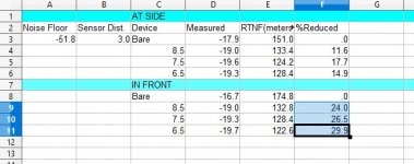
RMS values were calculated for each sample set. The RMS values for both recorder stations are in the following table.

DeviceSensor LocationRMS Power Measured dBNet (+/-) dB/Percent
BARESide-17.920
8.5Side-18.99-1.07 dB / - 22%
7.5Side-19.61-1.69 dB / - 32% See Note
6.5Side-19.32-1.40 dB / - 28% See Note
BAREFront-16.650
8.5Front-19.03-2.38 dB/ - 42%
7.5Front-19.51-2.86 dB/ - 48%
6.5Front-19.72-3.07 dB/ - 51%

Note: More samples would likely resolve this anomaly. This suggests there is a law of diminishing returns WRT to muzzle port diameter. A clearance of only 0.5mm over the radius of the bore isn't enough to be of any practical use. a clearance of 1.5mm over the radius of the bore is probably a bit excessive. It looks like a clearance of 1.0mm over the radius of the bore is in the "Goldylocks" zone. That half mm between 8.5 and 7.5 yeilds an additional 15% to 30% gain over that observed for the bore which is 3mm over caliber. This agrees with studies I did last year. I personally use 0.75mm over the radius of the bore (caliber + 1.5mm). That is a bit tight and prone to clipping particularly when the moderator is attached to a shroud.

Range to Noise Floor:
Now lets talk about a favorite number of mine which I call, "Range to Noise Floor". This number can be calculated from the data we have. It is the distance at which the moderator can not be heard because of the noise floor. There is no such thing as absolute silence in the real world. Ambient noise is that noise which exists in the environment at the time your making your shot or your measurements. It varies from situation to situation. This is also called the "noise floor". In RF communications it is called the same. If you signal is "in the noise floor" it takes very special equipment and sampling methods to pick it out. It can be done. It can not be done simply (or with your ears).

That calculation is explained in the post linked above. Here is that calculation for the data in the table above.
RTNF.jpg
I collected my data at 3 meters in two different locations so the chart shows the sensor distance as three meters and there are two sets of data, one for each sensor. Now then, this number is something you can call a "limit". It tells you that given perfect conditions at a noise floor of -52 dB the device under test slips below the noise floor (essentially becomes undetectable) at "X" yards for device "Y". So there is that.

Perhaps tomorrow I will run the graphs for the spectrum analysis of each moderator at each position.
 
Last edited:
OldSpook,

Thank you for taking the time and effort to collect and analyze the sound reduction data, using the 3 muffler set posted in the OP. I appreciate your efficiency.

The results you posted on your profile page speak for themselves. As you say, more data would be better, but in the absence of that, it seems there is some overlap with the result that others have reported in terms of dB reduction ranking. I wonder if the goldilocks bore size might change at much higher or lower FPE. Your power setting falls between that of the other data sets, which is useful to compare results.

As a side note, I designed each muffler to have the same baffle bore diameter, end to end. So, the size designations do not just apply at the endcaps. This is not of great importance, but I mentioned it because I often step open baffle bores towards the front of the muffler, when I have any doubts about angular alignment of the muffler to the barrel bore. Especially long skinny mufflers that have an integral outer tube made only of 3D printed plastic. Then, droop is a concern, especially if someone is likely to use PLA. PLA is stiff and strong, but not very creep resistant - especially at elevated temperatures, as might be reached in the trunk of a car parked in the sun. I prefer PETG, but can't control what material others choose to use.

It seems that my formula of 1 mm radial bore clearance with the projectile for my custom muffler designs is reasonable. I used to design tighter than that, but had too many clipping complaints. I kept increasing bore diameters until unexplained clipping went away. The main change that people reported was the lower tone of the larger baffle bores, with less sharpness to it. Since then, the projectile diameter + 2 mm is my assumed starting point, for all calibers. I know that many muffler bores are made 18 or 20% larger than caliber, rather than a fixed clearance. If an approach works, I have no arguments against it.

Thanks again for the valuable data, sound recordings and analysis you have generated and shared.
 
  • Like
Reactions: OldSpook
In light of the technology that reduces muzzle blast by deliberately leaking more gas ahead of the projectile, I have come up with the monstrosity below. It looks like Nicola Tesla and Werner Von Braun's love child - if such a thing were possible:

This muffler sports bypass ducts that flow air to the front chamber of the muffler, directly from the blast chamber. This, without "pointing" the duct openings directly at the frontal exit, to avoid transmitting shockwaves directly out.

The bypass ducts would act to some degree as a Tesla Valve, although 12 tubes each with a 3 mm bore diameter are not going to flow that much air. But the idea is to pipe a controlled volume of air into the last expansion chamber, so that it can leave ahead of the projectile (and ahead of the air) travelling down the sequential baffle bores; but without its energy, or more specifically, shock being being transmitted directly out the frontal bore. So the momentum of the piped air will need to stagnate in the last chamber, and turn around before leaking more gently out of the front bore.

Can this happen in the amount of time it takes the projectile to leave the front bore? This would seem like expecting the air to exit very suddenly, but yet merge with the ambient air more gently, is asking for a lot...

Will this contraption do anything useful or interesting? I don't know, but there is a way to find out. The zipped STL is attached for anyone wanting to have a go.

EDIT: V3 has a circular brace in the middle of the tubule span:


bypass LDC 7.JPG


bypass LDC 8.JPG


bypass LDC 5.JPG


bypass LDC 6.JPG


bypass LDC 4.JPG


bypass LDC 3.JPG


bypass LDC 2.JPG


bypass LDC 1.JPG


bypass LDC 9.JPG


bypass LDC braced2.JPG


bypass LDC braced.JPG


View attachment 7.5 mm bore with bypass vents V3.zip
 
Last edited:
Someone asked why all the complex ducts, when an outer sleeve would be simpler and could flow more air? Because the multi-tubular concept is what I woke up with. I captured it, preoccupied with how to model it (it was not easy), rather than why. My excuse is that this concept saves material, and that the goal is "some bypass flow"; not as much as possible - or as much as a full-on Tesla Valve would dictate.

I can change the duct ID and number of ducts easily, if that is a selling point :)

But, mostly I got the idea that long skinny tubes have acoustic damping properties from a guy posting on the GTA forum.

Also, I want to feed the air through the ducts fast to the front chamber. If the air first filled an annular plenum it would lag behind while "filling" that space.
 
Last edited:
  • Like
Reactions: IMADMAN
Someone asked why all the complex ducts, when an outer sleeve would be simpler and could flow more air? Because the multi-tubular concept is what I woke up with. I captured it, preoccupied with how to model it (it was not easy), rather than why. My excuse is that this concept saves material, and that the goal is "some bypass flow"; not as much as possible - or as much as a full-on Tesla Valve would dictate.

I can change the duct ID and number of ducts easily, if that is a selling point :)

But, mostly I got the idea that long skinny tubes have acoustic damping properties from a guy posting on the GTA forum.
That is something similar to what I have in my head.😁
 
  • Like
Reactions: subscriber
@subscriber Check this out:

Two radial expansion chamber rings, with ports in the middle, one folded backwards and one slightly longer folded forwards, might be applicable to moderator design.
The approach being to cancel sound waves/shockwaves with their own reflections.

Stacked baffles do this already in a way, and tilted baffles (a conical channel) increase the length of the individual channels, but they are all usually the same length and would only cancel a very specific frequency which just happens to have a wavelegth double the length of the baffle surface. A 3cm long baffle (measured along the conical surface) would cancel a 6cm wavelength which is about 6kHz. This would be too high; the spectrum of a shot is 0.5 to 5kHz. A 6cm long blind chanel/chamber would be needed to cancel out 3kHz.
Assuming all this can work, of course.
 
Last edited:
  • Like
Reactions: subscriber
@subscriber

Thread has wandered off topic but as I was working on something else I decided to comment further.

The test you designed shows that there is insufficient additional benefit to warrant running bore clearance any tighter than about 1.0mm clearance over the radius of the caliber. There is a significant improvement between 1.5mm radial and 1.0mm and a much smaller net in silencing between 1.0 radial and 0.75mm radial. I have therefore decided to open up my bore clearance on my own designs to 1.0mm. I will be sacrificing a small amount of silencing for end user convenience. Clipping is a PITA. It can easily be cured with a chain saw file used like a rolling pin to roll the moderator against on one's thigh. Unfortunately everyone doesn't have a chain saw file AND almost nobody wants to have to "finess" his moderator. People usually just want to attach the thing and have it running good from the start. So...

Thanks for motivating me to run the test for you. We have all gained.

EDIT: By the way, I sent the moderators back to Mike. ;)