• *The discussion of the creation, fabrication, or modification of airgun moderators is prohibited. The discussion of any "adapters" used to convert an airgun moderator to a firearm silencer will result in immediate termination of the account.*

Porous Moderator Design Tests

I hesitate to mention this, simply because it may be a dumb idea, but I'm considering making an acoustic tunnel out of duct board for my experiments. Have located a local place to get the duct board. I'll fab a rectangular tunnel and fire through it. Should knock down the room echo some. If more cancellation is needed, structures can be placed to knock down the acoustic energy in key places. Kind of like building an special built anechoic chamber. Could be a total failure, but hey it's worth a try to get a somewhat more stable acoustic setup here.

I think this is a great idea and has been on my todo list for a while.
I'm thinking about something similar at the other end to deal with the noise from the trap.
My gear is quiet enough for the opportunistic shot here and there... but it's not undetectable. If I'm shooting targets there are too many opportunities for someone to listen close enough and figure out what is going on.
Currently shooting at a rubber mulch trap in a cardboard box. There's definitely a slap upon impact and it's noticeable outdoors. The shot is relatively quiet then the thwap some time later. An acoustic tunnel will definitely change the directionality of the sound, so that it is considerably less in directions say more than +/-20 degrees off axis, if the tunnel has some decent length. This is not to say that there won't be acoustic sidelobes, like an antenna, or diffraction, but it is a good start.

Indoors, well there is not as much delay to the target, since the distances are shorter. For indoor testing, I may make a replaceable end that I shoot through that is mounted on the trap itself. It all depends on how cheap this duct board is, and how I can get it home. Think it comes in 4x8 foot sheets and optionally longer. It comes in 1", 1.5" and 2" thicknesses. The thicker it is the more it attenuates low frequencies. How well it works for this "unconventional" application is totally unknown to me. I do know that plain pink fiberglass insulation if in a tube like form has pretty high attenuation, but I don't want to deal with trying to stuff it in sonotubes and being not rigid enough and requiring internal support. It would be a tough material to work with, although relatively cheap. The duct board is more rigid and designed to be made into ducts.
 
@OldSpook I am finding that there is not enough time before and after the merged audio files to adequately window the signals to get good measurements. It would be better if there was say 1 second of time before and after the shot to be able to get good signatures from the wav file. If there isn't dead time before and after the signal, then the window function significantly truncates the signal. I want to have enough signal to see it fully decay - which doesn't seem to be the case for the higher amplitude shots. It would be good to have the audio return to ambient at the end of each shot, as it would set the noise floor more appropriately. I do realize these are outdoor shots and stuff happens, like wind noise. I have the same thing even when testing indoors as my test room is relatively near a street and I get cars going by. I have to toss those datasets.

I will try to extract the audio out of the video you (temporarily) uploaded. Pretty sure that will have enough time between shots to get good extractions. Also noticed in the audio file there were two channels, but they looked identical. If so, that makes the file larger than it ought to be (by a factor of 2). Think you can extract the audio using vlc, but it is an ugly long command string to run. The instructions are for Windows, but I'm running a Mac. I'll give it a try though. If that doesn't work, I'll look around some more. From watching both videos, I think you try an Ember, and a pure porous, with and without a wrap of duct tape, is that correct?
Using VLC open "Media"->"Convert Save"->"+ ADD" your file. Click "Convert Save". Create a different file name to save too (buggy in windows) and save as an .flac. Import the flac file into Audacity.

EDIT: The audio channels are different. The microphones are pointed toward and away from the signal source and are about 180mm apart. It appears that I lied. I have read the manual and double checked there is only one port for a microphone on that Moto-G XT2041DL. I'll have a look at some traces because they definitely are different in the right and left channels. I have no idea why that would be the case unless there is a microphone I have not found.

The moderators used in this video are from the same stl file. The stl file is an Ember moderator 35mm x 100mm with two Tesla Baffles as described elsewhere by OldCrow ;) I also see one up in this thread where I tested a PETG against TPU. The video is in that post.

View attachment porous-vs-solid.zip

Also attached is an image of the Ember in cross section.

Ember-17.jpg
 
Last edited:
@OldSpook Thanks. I just tried doing this in the command line and I find that at least for all 6 shots in the DSCN0292.MOV file, the resultant wav file is clipped. Command line I used, from the vlc website. $
vlc -I dummy -vv "DSCN0292.MOV" --sout "#transcode{acodec=s16le,channels=2}:std{access=file,mux=wav,dst=duct_tape_spook.wav}" vlc://quit
Screenshot 2024-01-28 at 1.09.08 PM.png

Since I put in the -vv flag, I could see vlc used 48.000 KHz for the wav file, rather than 44.1 KHz. Don't happen to recall if this means there's resampling. Could be that is what videos use. The wav file might be reduced to 16 bits, rather than 32 - the verbose output is a little confusing.

Think I'll try the conversion your way.

But a simplistic look at these 6 shots shows clipping multiple times per shot. The first shot was clipped 3 times. It's difficult to get good quality estimates if an unknown amount of energy is being removed. Now, I don't know if the clipping is at source level (ie in the video) or as a result of the transcoding. Just not sure of the transcoding algorithm. I'd like to be able to attenuate the audio channels 10 dB and re-encode to see if the audio is flat topped at it's peak extent. Not sure how to do that at the moment, but the day is still young.
 
@OldSpook Thanks. I just tried doing this in the command line and I find that at least for all 6 shots in the DSCN0292.MOV file, the resultant wav file is clipped. Command line I used, from the vlc website. $
vlc -I dummy -vv "DSCN0292.MOV" --sout "#transcode{acodec=s16le,channels=2}:std{access=file,mux=wav,dst=duct_tape_spook.wav}" vlc://quit
View attachment 429763
Since I put in the -vv flag, I could see vlc used 48.000 KHz for the wav file, rather than 44.1 KHz. Don't happen to recall if this means there's resampling. Could be that is what videos use. The wav file might be reduced to 16 bits, rather than 32 - the verbose output is a little confusing.

Think I'll try the conversion your way.

But a simplistic look at these 6 shots shows clipping multiple times per shot. The first shot was clipped 3 times. It's difficult to get good quality estimates if an unknown amount of energy is being removed. Now, I don't know if the clipping is at source level (ie in the video) or as a result of the transcoding. Just not sure of the transcoding algorithm. I'd like to be able to attenuate the audio channels 10 dB and re-encode to see if the audio is flat topped at it's peak extent. Not sure how to do that at the moment, but the day is still young.
You can repair clipping by attenuating the entire file the same amount. That is available "Effect"->"Noise Removal and Repair"->"Clip Fix". Start with a half dB. They are clipped but not badly. I have since relocated the microphone to preclude clipping.
 
  • Like
Reactions: WobblyHand
Using VLC open "Media"->"Convert Save"->"+ ADD" your file. Click "Convert Save". Create a different file name to save too (buggy in windows) and save as an .flac. Import the flac file into Audacity.

EDIT: The audio channels are different. The microphones are pointed toward and away from the signal source and are about 180mm apart. It appears that I lied. I have read the manual and double checked there is only one port for a microphone on that Moto-G XT2041DL. I'll have a look at some traces because they definitely are different in the right and left channels. I have no idea why that would be the case unless there is a microphone I have not found.

The moderators used in this video are from the same stl file. The stl file is an Ember moderator 35mm x 100mm with two Tesla Baffles as described elsewhere by OldCrow ;) I also see one up in this thread where I tested a PETG against TPU. The video is in that post.

View attachment 429753

Also attached is an image of the Ember in cross section.

View attachment 429764
Thanks for adding in the zip file and image. The first flac file is clipped, at least Audacity thinks so.
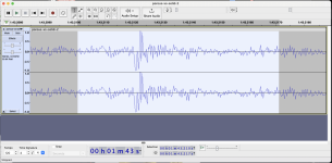
Here's a picture zoomed in on the second file. One of the earlier shots. You can see the flat tops. We can discuss how much is "missing", but none of us really knows...
Screenshot 2024-01-28 at 1.57.35 PM.png
This is not meant to be a criticism in any way. It's darn hard to get good quantitative measurements, even relative ones.

In this particular shot there was a secondary signal about 15ms later. That corresponds to a round trip distance of 2.25m, if we use the speed of sound of 300 m/second. Was there a wall, or tree nearby anywhere around that distance? Or some corner that could act as a corner reflector? Or is that some kind of valve bounce? Not that much of an AG wizard to know what valve bounce times are.

We are getting there. This is not easy stuff to do.
 
Thanks for adding in the zip file and image. The first flac file is clipped, at least Audacity thinks so.
Here's a picture zoomed in on the second file. One of the earlier shots. You can see the flat tops. We can discuss how much is "missing", but none of us really knows...
View attachment 429781
This is not meant to be a criticism in any way. It's darn hard to get good quantitative measurements, even relative ones.

In this particular shot there was a secondary signal about 15ms later. That corresponds to a round trip distance of 2.25m, if we use the speed of sound of 300 m/second. Was there a wall, or tree nearby anywhere around that distance? Or some corner that could act as a corner reflector? Or is that some kind of valve bounce? Not that much of an AG wizard to know what valve bounce times are.

We are getting there. This is not easy stuff to do.
Audacity can project by the slope of the rising "points" how much is clipped and can attenuate the entire sample to recover the missing data. You can then either just use the numbers which result or add back in the amount you attenuated the clip to get "repeatable" numbers.

When you "Fix" a clipped section, it is likely there is some loss of data but if you expand that time line until you can see the individual sound samples and then attenuate by 1/2 dB at a time you will see that you are not loosing enough data to make a whole lot of difference (perhaps on the order of 1/100 of a dB over the sample)... That estimate is probably rough order of magnitude anyway.

Before Correcting:
1706471544949.png


After Correcting (-1.5 dB global attenuation)
1706471604575.png
 
You can repair clipping by attenuating the entire file the same amount. That is available "Effect"->"Noise Removal and Repair"->"Clip Fix". Start with a half dB. They are clipped but not badly. I have since relocated the microphone to preclude clipping.
I didn't know about that tool. Interesting. It does raise a question or two.

Does this imply that the wave file isn't clipped to begin with, but is a result of their scaling algorithm, or are they actually altering the waveform? As a long time engineer, there's a suspicion of voodoo or assumptions. I need to try it with the same file with and without to compare them to convince myself. Audacity's assumptions may be perfectly valid for general audio, but might not be valid for impulsive signals, which we certainly have. At this point, it isn't clear to me how to bound the errors due to Audacity's estimator, this is outside of my knowledge area. Or I'm missing some key bit of information.

Maybe you know this, is there a way to finely scroll through the data? It's easy at a gross level, but I want to scroll at sample level. Just using the slider results in the data zooming by.
Take your sample and find a place where it's clipping.

Take careful note of the exact time.

Trim the clip from both ends so that you only have a couple of milliseconds of time around the point of clipping maybe five.

Again note the time of the clipping.

Expand (zoom) the timeline until you see individual sample points.

Using the fix clipping option under effects, set it up to attenuate the entire sample by some tiny amount when you fix clips.

You can now use control r to attenuate the entire sample by that tiny amount each time you press it.

That will let you actually watch how much each sample point is attenuated.

EDIT: Wikipedia Exerpt:
Temporal summation is the relationship between stimulus duration and intensity when the presentation time is less than 1 second. Auditory sensitivity changes when the duration of a sound becomes less than 1 second. The threshold intensity decreases by about 10 dB when the duration of a tone burst is increased from 20 to 200 ms.

For example, suppose that the quietest sound a subject can hear is 16 dB SPL if the sound is presented at a duration of 200 ms. If the same sound is then presented for a duration of only 20 ms, the quietest sound that can now be heard by the subject goes up to 26 dB SPL. In other words, if a signal is shortened by a factor of 10 then the level of that signal must be increased by as much as 10 dB to be heard by the subject.

They are talking in terms of 20 ms and 200 ms. We are worrying about 5 consecutive samples at 44100 Hz (0.0001134 sec). When THAT bomb goes off you don't hear it. It just destroys your ear drums and possibly other soft tissues. o_O You might want me to run those tests again and I can do that.
 
Last edited:
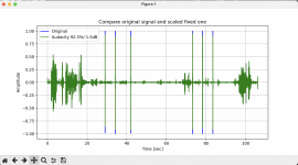
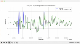
I did a rude and crude repair clipping exercise. I set the threshold of clipping to 92.5%, and reduced the amplitude by -1.5dB. I compared the unmodified file to the clip restored file, by plotting them on the same graph. I then chose a region outside of any clipping to find the amplitude difference. In my case I found a peak that measured 0.3646 in the original, and 0.3068 in the attenuated/clip restored file. Then I multiplied the attenuated file by that ratio (0.3646/0.3068) to make the amplitude the same. Then I plotted the waveforms on top of each other and zoomed in where they differ. What I find is the clip/restored + gain peaks are lower amplitude than the clipped peaks. This means that the peaks are being suppressed and not the true amplitude. We already know that clipped peaks are lower than the real signal (by definition). But now I see that at least using Audacity's algorithm, the peaks are not remotely accurate. I'm not surprised in the least, as Audacity is trying to make things sound better from an audio perspective - not to faithfully restore the signal to what it would have been.

The green is the altered and scaled waveform. It has nearly identical fit to the original, except where there was clipping. The green waveform is always less than the blue in the shot area. I don't know, but this doesn't seem like a faithful signal restoration. May sound good, but the algorithm is discounting high frequency energies. First attachment is a detail view, second is the big picture.
Screenshot 2024-01-28 at 4.33.12 PM.pngScreenshot 2024-01-28 at 4.35.54 PM.png
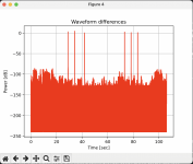
Every shot looks similar. If you "do python" I can send you the file I used to process the data. I'm not doing sophisticated processing for this, but the graphing ability is similar to matlab, which makes it very handy. It didn't have much trouble plotting that 4677100 point graph, nor did it give me any trouble to zoom in or pan the waveform. If I take the difference between the waveforms, the peak error outside of the shots is 5e-5, which for our purposes is very small. But in the shot, the error is full scale for more than a couple of samples. Think we need to do better if our measurements are going to withstand scrutiny. Here is the difference in dB's since it shows it is very good EXCEPT for the impulses. The RMS value of the difference of the waveforms is 6.45, or 16.2 dB. I can assure you the -85dB errors are insufficient to add up, it's all in the very peaks we are trying to measure. Having that kind of error indicates to me that Audacity clipping restoration algorithm is not adequate for the kind of measurement we are pursuing.
Screenshot 2024-01-28 at 5.00.20 PM.png
What are your thoughts on this? Maybe I'm doing something really wrong? If so, tell me in a way so things can improve. It was fun to try this correction, and it works very well on non-impulsive sound, far better than I thought.
 
I did a rude and crude repair clipping exercise. I set the threshold of clipping to 92.5%, and reduced the amplitude by -1.5dB. I compared the unmodified file to the clip restored file, by plotting them on the same graph. I then chose a region outside of any clipping to find the amplitude difference. In my case I found a peak that measured 0.3646 in the original, and 0.3068 in the attenuated/clip restored file. Then I multiplied the attenuated file by that ratio (0.3646/0.3068) to make the amplitude the same. Then I plotted the waveforms on top of each other and zoomed in where they differ. What I find is the clip/restored + gain peaks are lower amplitude than the clipped peaks. This means that the peaks are being suppressed and not the true amplitude. We already know that clipped peaks are lower than the real signal (by definition). But now I see that at least using Audacity's algorithm, the peaks are not remotely accurate. I'm not surprised in the least, as Audacity is trying to make things sound better from an audio perspective - not to faithfully restore the signal to what it would have been.

The green is the altered and scaled waveform. It has nearly identical fit to the original, except where there was clipping. The green waveform is always less than the blue in the shot area. I don't know, but this doesn't seem like a faithful signal restoration. May sound good, but the algorithm is discounting high frequency energies. First attachment is a detail view, second is the big picture.
View attachment 429834View attachment 429835
Every shot looks similar. If you "do python" I can send you the file I used to process the data. I'm not doing sophisticated processing for this, but the graphing ability is similar to matlab, which makes it very handy. It didn't have much trouble plotting that 4677100 point graph, nor did it give me any trouble to zoom in or pan the waveform. If I take the difference between the waveforms, the peak error outside of the shots is 5e-5, which for our purposes is very small. But in the shot, the error is full scale for more than a couple of samples. Think we need to do better if our measurements are going to withstand scrutiny. Here is the difference in dB's since it shows it is very good EXCEPT for the impulses. The RMS value of the difference of the waveforms is 6.45, or 16.2 dB. I can assure you the -85dB errors are insufficient to add up, it's all in the very peaks we are trying to measure. Having that kind of error indicates to me that Audacity clipping restoration algorithm is not adequate for the kind of measurement we are pursuing.
View attachment 429853
What are your thoughts on this? Maybe I'm doing something really wrong? If so, tell me in a way so things can improve. It was fun to try this correction, and it works very well on non-impulsive sound, far better than I thought.
Well I think you have done the math. Your reasoning is sound enough for me to run the tests again. As I mentioned in a different post I moved my microphone to preclude clipping as I am also an engineer and any amount of uncertainty is more than I like to accept.

That said I am inclined to suggest you add 30 dB to the clipped points and run RMS comparisons of the first 20 ms of each shot (given you have the time). I think you'll see that the clipping isn't changing the outcome.

Never the less, lets work up the criteria for another test and Ill build the moderators test them and then send them to you to test.

What do you think?
 
Last edited:
@WobblyHand If you are game for that I have a design that I'd like to use but if you have one we can go with that. Check this and tell me what you think.
  • I suggest I build two moderators each in PETG and TPU.
  • I usually put sleeves on them but I can print them as one piece. I'd rather build them with CF tube.
  • I have plenty of 1/2 UNF by 20 helicoils and I can print them right into the units.
  • I make my moderators in 4 pieces now. I print both end caps in resin on an MSLA printer, the baffle section in one piece on an FDM printer of the chosen plastic, and I use CF tube as the outside tube structure.
  • Solid moderators will be solid completely. Gyroid infill moderators will be 40% infill in all points except the areas which must be reinforced (endcaps and attachments).
  • I glue everything up with West System epoxy. It makes for a nice, strong, light and presentable package.
  • Assuming you agree I will build them like that.
  • They will be 30mm OD x 28mm ID x ~130mm long.
  • The BORE will be CALIBER + 3.0mm
  • The muzzle exit will be CALIBER + 2.0mm
  • They will contain two Tesla Diode type baffles and an expansion chamber.
  • Each baffle will take up one third of the total "stack" volume.
  • One baffle will be at the muzzle end and one baffle will be at the rifle end.
  • The expansion chamber will be between those baffles.
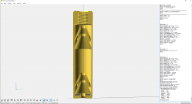
  • Exact dimensional specifications are calculated in the code whenever I generate an STL file and I'll make those outputs availale as a text file (and make myself available to interprete those print statements).

I have attached a cross section of the moderator I am thinking of using and I suggest .17 caliber unless you don't have a gun in .17 in which case I can do them in .22 as easily. My test gun will be the Stormrider .17 I have which is shooting around 18 fpe. I nee your input on the caliber.

1706483741684.png

This should give us what we need to compare apples to apples in two different mediums. We are doing real engineering here, which costs REAL money in the real world. If you don't have the time for it, I understand. I will endeavor to persevere. 😁


Either way you can check my work.
 
Well I think you have done the math. Your reasoning is sound enough for me to run the tests again. As I mentioned in a different post I moved my microphone to preclude clipping as I am also an engineer and any amount of uncertainty is less than I like to accept.

That said I am inclined to suggest you add 30 dB to the clipped points and run RMS comparisons of the first 20 ms of each shot (given you have the time). I think you'll see that the clipping isn't changing the outcome.

Never the less, lets work up the criteria for another test and Ill build the moderators test them and then send them to you to test.

What do you think?
One can look at this a couple of ways. Can't say that I disagree with you at the moment, but it will take a bit to overcome some of my discomfort. I think I will grab one of the shots and compare the original to the Audacity altered one. Maybe the energy loss isn't that much... At the moment I don't have a gut feel for this - and I know enough not to trust my gut right now. I can see that it is single points that differ. Depending on the dataset size the single points might matter, but for large sets it could be irrelevant. I'll check out that thought later tonight. I'm thinking about the integrated power, and perhaps the spectral distribution.

Yeah, I'll take up your offer. Let me know whenever you need my personal details.
Fair enough. Give me your thoughts about the above parameters and don't worry too much with that problem. We can eliminate it by redoing the test. I agree that clipping is bad either way. I was just too darn lazy to go run the test again.
 
Shoot there is one other thing I should mention. Compare this to the one linked in the post above.
1706486244950.png

When I print with TPU I have decided to run the "thickness" (see TK in the side comments) parameter at double what I run it with PETG. This (I believe) improves the function of the baffles with sparse infills. I only do this right now for TPU as I have not felt the need to strengthen the structure with PETG (as I did with TPU). I don't think this will give us a problem in this test because we are testing solid material X against gyroid material X. Both TPU mods are identical except for the infill parameter and both PETG mods are identical as well.

I need your agreement on doing it this way (or I can patch the code (I'd rather not))?
 
Seems we were writing at the same time (twice now!). I'd prefer 22 cal if possible. I could convert my pistol to .177 though.
You can do what is easier for you now. Don't patch the code for what you just posted. TPU definitely requires a little help in the design, vs PETG, add whatever thickness you need to maintain the part integrity.

What did you mean by:
  • The BORE will be CALIBER + 3.0mm
  • The muzzle exit will be CALIBER + 2.0mm
Does this mean the muzzle exit by the barrel, (the input of the LDC,) or the muzzle exit of the LDC is 5.5+2 = 7.5mm? Hadn't seen this nomenclature before, so wanted to make sure I understood.
 
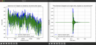
FYI, if I just chop out +/- 0.49 seconds around a shot and compute the rms of the signal between the two options, the Audacity reconstructed option is is 1.87 dB below the original. So it is not a good method of recovery of the signal for this purpose. The FFT is lower energy as well, as it should be, since the energy in the time domain equals the energy in the frequency domain according to Parseval's theorem. You can see the green waveform is nearly always less than the blue, in both domains.
Screenshot 2024-01-28 at 8.27.51 PM.png
So my uneasiness is justified. If we want to have data that turns into reliable quantitative results, no clipping. Audacity slights of hand will not fix the problem. Things that seem too good to be true, often are. If one throws away information, it's practically impossible to recover it.
 
  • Like
Reactions: OldSpook
Seems we were writing at the same time (twice now!). I'd prefer 22 cal if possible. I could convert my pistol to .177 though.
You can do what is easier for you now. Don't patch the code for what you just posted. TPU definitely requires a little help in the design, vs PETG, add whatever thickness you need to maintain the part integrity.

What did you mean by:
  • The BORE will be CALIBER + 3.0mm
  • The muzzle exit will be CALIBER + 2.0mm
Does this mean the muzzle exit by the barrel, (the input of the LDC,) or the muzzle exit of the LDC is 5.5+2 = 7.5mm? Hadn't seen this nomenclature before, so wanted to make sure I understood.
The bore of the moderator (baffle clearance) = 0.22*25.4+3.0.
The exit at the muzzle of the moderator will be 0.22*25.4+2.0.
This establishes clearances. They might be a bit tight but we are working on moderation comparison vice accuracy.
I will do it in 0.22 and any differences will be done inside the Slic3r (Prusa Slicer). There will be only one STL file. There is no harm (to the comparison) running thicker baffles in all cases.

ATTACHED STL FILES

View attachment SvsP-Test-Attach.zip
 
Last edited:
  • Like
Reactions: WobblyHand
The bore of the moderator (baffle clearance) = 0.22*25.4+3.0.
The exit at the muzzle of the moderator will be 0.22*25.4+2.0.
This establishes clearances. They might be a bit tight but we are working on moderation comparison vice accuracy.
I will do it in 0.22 and any differences will be done inside the Slic3r (Prusa Slicer). There will be only one STL file. There is no harm (to the comparison) running thicker baffles in all cases.

ATTACHED STL FILES

View attachment 429940
Have the files.

Now to slice. Seem to be getting an unexpected internal perimeter, although I have set them to 0 in the slicer. I'll have to muck about with that to see what's causing this. Edit: Found out how to fix that.

ID is 28mm? Just confirming before sourcing CF tubing. Found some for $30.50 for 1 meter. Need to order before Chinese New Years, or it will be delayed a while.
 
Last edited: