• *The discussion of the creation, fabrication, or modification of airgun moderators is prohibited. The discussion of any "adapters" used to convert an airgun moderator to a firearm silencer will result in immediate termination of the account.*

Porous Moderator Design Tests

Man! Deciding just exactly where to grab the start of a sample (spotting the uncorking) is HARD without that LASER switch Stan is using! Just whipping my butt here today.

I have just about concluded the lack of a proper triggering device requires deeper statistical analysis unless you just want relational (ranking) data. It is pretty easy to measure them well enough to rank them in order of performance WRT quieting but it's a whole lot harder to get repeatable quantitative data without a deterministic starting point in the shot cycle.

I have shot the end out of one of the glue ups and am going to have to print another endcap. Tomorrow I have to do range safety officer so that day is a down day. I'll get these in the mail by Friday. Word.
Generally for analysis, I just bracket the main peak of the waveform with a generous amount of silence before and after. I'm looking for an excess of ~ 16K samples, give or take, in the whole set. This is assuming there is some level of acoustic silence before and after the waveform. Wind noise, or clicking, cocking the AG, or talking within ~0.5 seconds of the shot is difficult to get rid of.

Looking at yesterdays dump, I see it has been very difficult to get non clipped shots. You do have some unclipped shots, so I will look at them. (Unfortunately we cannot get a statistically meaningful sense since the number of data sets is too low. For that one would need at least 22 good shots, which is far beyond what either I or anyone else would deem reasonable to collect.)

This means, probably, that the microphones are still a tad too close. I realize it is a battle between dynamic range of the mic and getting meaningful data. Remember, we get process gain by using an FFT and can observe features below the noise floor. I used to do this regularly in my radar work. Also remember, from Parseval's theorem we can recover the total energy in either domain, simply by summing the squares of the signal and adding them up. To make the spectral energy equivalent to the time domain is a simple multiplicative factor. It may be advantageous to measure the energy in the frequency domain, since the final bandwidth of each FFT bin is N times less than the the sample rate, where N is the size of the FFT. This means the SNR of each of the bins is effectively N times greater than a single sample in the time domain, since we are simultaneously using all the samples in the spectral domain. The downside of using the spectral domain is time information has been "erased". But energy is energy, no matter which domain. And we know that higher frequencies correspond to the crack that we hear. We humans DF (direction find) pretty well on higher frequencies rather than lower bass like frequencies.
 
Generally for analysis, I just bracket the main peak of the waveform with a generous amount of silence before and after. I'm looking for an excess of ~ 16K samples, give or take, in the whole set. This is assuming there is some level of acoustic silence before and after the waveform. Wind noise, or clicking, cocking the AG, or talking within ~0.5 seconds of the shot is difficult to get rid of.
I can see that I am going to have to work on my setup. I'll need some wind better wind damping.
Looking at yesterdays dump, I see it has been very difficult to get non clipped shots. You do have some unclipped shots, so I will look at them. (Unfortunately we cannot get a statistically meaningful sense since the number of data sets is too low. For that one would need at least 22 good shots, which is far beyond what either I or anyone else would deem reasonable to collect.)

Yeah, don't bother with the video MOV file. That camera was only about 5 feet from the muzzle and was clipping badly. There should be a readme there that explains it. I was triggering the phone (@ 45 degrees & 9 feet range, 40" AGL) with my voice and then taking the shot. That audio only WAV file does not show any clipping in Audacity.

This means, probably, that the microphones are still a tad too close.
Yes the camera mic was too close. I can move the microphone fairly easily and it might need to be out there another 3 yards or so.
I realize it is a battle between dynamic range of the mic and getting meaningful data. Remember, we get process gain by using an FFT and can observe features below the noise floor.
;P Yes I do remember that. :) They are doing pretty amazing things with very low data rate signaling on the HAM bands these days.
I used to do this regularly in my radar work. Also remember, from Parseval's theorem we can recover the total energy in either domain, simply by summing the squares of the signal and adding them up. To make the spectral energy equivalent to the time domain is a simple multiplicative factor. It may be advantageous to measure the energy in the frequency domain, since the final bandwidth of each FFT bin is N times less than the the sample rate, where N is the size of the FFT. This means the SNR of each of the bins is effectively N times greater than a single sample in the time domain, since we are simultaneously using all the samples in the spectral domain. The downside of using the spectral domain is time information has been "erased". But energy is energy, no matter which domain.
True I was overly concerned about echo cancelling by elimination. I opened up my sample window based upon this and that helps.
And we know that higher frequencies correspond to the crack that we hear. We humans DF (direction find) pretty well on higher frequencies rather than lower bass like frequencies.
Only if we still HAVE those higher frequencies... =P I've got 105 dBs of Tinitus at 4kHz on one side and 110 on the other... You learn to not to listen to it.
 
That audio only WAV file does not show any clipping in Audacity.
Not in the 3 files I looked at. There's clipping in nearly every file, some worse than others. I just turn on show clipping and there's bright red lines showing the location. To be fair, some are not terrible clips, but there's still a lot of clips which make it hard to get say 3 good shots in a single channel. Sometimes one mic clips and the other does not, or both clip. Audacity isn't shy about identifying clipping - maybe they are aggressive about it, but every case that Audacity said was clipped (that I looked at carefully) was clipped. If the little sample square is truncated in anyway, ie not square, the signal is clipped. If the signal is sitting at +1 or -1, it's highly likely to be clipped. I'll admit it might not be, but there's no way to prove one way or the other. However, if the absolute value of the sample is less than 1 then it's nearly certain it is not clipped. Instrumentation grade measurements are hard, there's no way about it. Little stuff matters. I don't find these measurements any easier than you do. There's a million ways to muff the experiment.
 
Last edited:
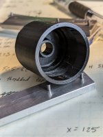
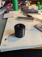
FYI, to anyone who wants to print fine threads, I just managed to print 32TPI threads on both a male and female piece and screw them together for 11mm, as printed. Took 0.1mm layer heights. Also required a wrench and a little bit of lubrication, but it did work. Well, it did work on a sample set of one...
PXL_20240131_182036366.jpgPXL_20240131_182005712.jpg
I was thinking of screwing in the end caps, so I could just swap cores without gluing. Not for manufacturing purposes, but to reduce the amount of stuff to print for testing. This was not printed slowly, both pieces were printed in "speed & detail mode" with 0.1mm layer height on the MK4 with IS.
 
  • Like
Reactions: OldSpook
How are the printed threads holding up to repeated pressure cycles? Any failure? I machine my mods out of aluminum until last year when I got my printers. So far I only printed internals for my aluminum housings and end caps.

I tried printing the full suppressor file that subscriber put in a different thread. That went pretty good except the threads in the end cap are not perfectly square but good enough I could try it on my .177. I feel like those 1/2 - 20 threads will fail at some point when used on higher power rifles. Plus the issue of not being perfectly square.
 
FYI, to anyone who wants to print fine threads, I just managed to print 32TPI threads on both a male and female piece and screw them together for 11mm, as printed. Took 0.1mm layer heights. Also required a wrench and a little bit of lubrication, but it did work. Well, it did work on a sample set of one...
View attachment 430638View attachment 430639
I was thinking of screwing in the end caps, so I could just swap cores without gluing. Not for manufacturing purposes, but to reduce the amount of stuff to print for testing. This was not printed slowly, both pieces were printed in "speed & detail mode" with 0.1mm layer height on the MK4 with IS.
Not sure how you are creating your threads... But if you need a little extra clearance, in Fusion360 you can select the face of the thread (one for each face of the helix) and do a small negative extrusion. Maybe .1mm or something. I eventually copied Fusion's library file that had the metric thread specifications and adjusted the settings for the thread forms I was using until they worked straight off the printer.
 
How are the printed threads holding up to repeated pressure cycles? Any failure? I machine my mods out of aluminum until last year when I got my printers. So far I only printed internals for my aluminum housings and end caps.

I tried printing the full suppressor file that subscriber put in a different thread. That went pretty good except the threads in the end cap are not perfectly square but good enough I could try it on my .177. I feel like those 1/2 - 20 threads will fail at some point when used on higher power rifles. Plus the issue of not being perfectly square.
They have not been tested to repeated pressure cycles, like in normal life. I wouldn't use these fine threads that way. This would only be for testing cores to see which one's are better. So maybe a couple hundred shots? I have not even finished building this one, maybe it will fail right away. I don't think it will, but I will find out soon enough.

Printed threads "should be" on bore and perfectly square in the original CAD file. They'd better be, or there's an error in the original design. I would say that for repeated use, actually constant swapping on on off an AG, threads with metal inserts (if properly installed) are superior. Better yet is a metal end piece which has threads for the adapter, and perhaps for the exterior case of the LDC. It's really a mechanical design issue of stack ups. I like to machine my own moderator adapters on my lathe. I make a flange on the end, which looks a little goofy, but since it is turned in a collet, it acts as a flat reference for the LDC to seat on.

Threads should never be the reference surface, simply because most of us have not machined both parts as a set. Threads have slop to them, actually by design, else they would be too tight to turn. So anyways, I have a wide flange on the adapter, and I tend to turn the end of the LDC in a lathe so that they should mate and not have tilt of the LDC bore relative to the flange. There's a lot of stuff that can go wrong as you might imagine. There's no guarantee the muzzle hole is in the center of the barrel - it happens. Sometimes they are off.

Plastic threads are relative fragile. They won't last as long as good metal threads. But for occasional use they are fine. Just be very careful to make sure you start them properly, and are lightly snugged to the reference surface. And don't put any weight on your moderator, because they are plastic and they can bend or yield.

Printed moderators are relatively economical, but they do have limitations. "Nice moderators" made of superior materials, well, they are better. The purpose of this thread is to check on various designs to see which works better in a quantitative sense. There are posts reviewing moderators for other characteristics, but I think that is not the focus of this thread. But those are my words, not that of the original poster.
 
How are the printed threads holding up to repeated pressure cycles? Any failure? I machine my mods out of aluminum until last year when I got my printers. So far I only printed internals for my aluminum housings and end caps.

I tried printing the full suppressor file that subscriber put in a different thread. That went pretty good except the threads in the end cap are not perfectly square but good enough I could try it on my .177. I feel like those 1/2 - 20 threads will fail at some point when used on higher power rifles. Plus the issue of not being perfectly square.
I haven't had any issues with printed threads (once I had adjusted them to print to proper dimensions)
On my barrel I had a machined face/shoulder, just past the end of the threads.
I designed the moderator to thread on and tighten against that shoulder to help ensure it was square to bore.

If I was really worried about it and had a gun that didn't use a shroud, I would design the rear end cap so that it could fit (snuggly) over the barrel, extending well past the threaded portion. This additional length/contact surface would help ensure that the moderator remained concentric to the barrel, and wouldn't rely so heavily on the threads.
 
  • Like
Reactions: OldSpook
Not sure how you are creating your threads... But if you need a little extra clearance, in Fusion360 you can select the face of the thread (one for each face of the helix) and do a small negative extrusion. Maybe .1mm or something. I eventually copied Fusion's library file that had the metric thread specifications and adjusted the settings for the thread forms I was using until they worked straight off the printer.
I reviewed the CAD files and inserted the pieces in a common file to review clearances. Fiddled with making the threaded pieces a little larger OD for the inside thread and a little smaller for the male thread. If printed without blurbs, it will fit. But sometimes there are blurbs in the filament or the printed piece. Might be filament quality, or adequate dryness, but every so often there's an errant fiber or tiny blob that lands in the thread area. At least for the male thread it is easy to inspect. The female piece is more difficult, especially if printed in black - stuff is hard to see!

I'm using FreeCAD, (originally on Linux, now on a Mac) so it comes with all sorts of predefined threads, rods, taps and stuff like that. Even so, it pays to inspect the files for clearance. So I can say I did my homework. I have also created custom thread forms for various purposed. The CAD program is usually not the limiting factor, it's the operator. Likewise for printing, there's loads to learn about the interesting things to tweak a printer and the slicer.
 
Printed threads "should be" on bore and perfectly square in the original CAD file. They'd better be, or there's an error in the original design. I would say that for repeated use, actually constant swapping on on off an AG, threads with metal inserts (if properly installed) are superior. Better yet is a metal end piece which has threads for the adapter, and perhaps for the exterior case of the LDC. It's really a mechanical design issue of stack ups. I like to machine my own moderator adapters on my lathe. I make a flange on the end, which looks a little goofy, but since it is turned in a collet, it acts as a flat reference for the LDC to seat on.
Thats the problem with fully printed mods that are longer. The cad drawing will be prefect but the nature of 3d printing and how the plastic behaves as it cools or any issues that might pop up during printing will in my opinion cause alignment issues. I also have doubts of how long the threads will hold up in real world use. Probably wasnt the right thread to ask about experience with longevity of printed threads. I dont want to hijack the thread so my apologies. I think I will stick with machining my end caps and printing the baffles.
 
Not in the 3 files I looked at. There's clipping in nearly every file, some worse than others.
I've looked at them again. The only way I can find clipping is to turn the clipping start/stop thresholds to 1 over 1 vice the default of 3/3. That shows some clipping. I think any clipping could be a problem and I will take the steps to do the test again to ensure that there is no clipping but I also think the clipping you are seeing is choking on the gnat.

Suppose your sample set for one shot consists of 10ms (which is probably about right) but we just kicked around the idea of how hard it is to decide exactly when to start that set so ... suppose your set consists of 10ms sampled at 44100 Hz. That is going to work out to 441 samples. The average energy that any individual sample in that set represents will be 2.27 percent. If you are looking at RMS across that entire domain and you have one or two samples which clipped because twice what the sensor can handle you are still only looking at perhaps 5% error. When you express 5% error in dB you get ~0.2225 dB. It's just not enough to worry about. When I set my clipping to the Audacity default I see no clipping.
I just turn on show clipping and there's bright red lines showing the location. To be fair, some are not terrible clips, but there's still a lot of clips which make it hard to get say 3 good shots in a single channel. Sometimes one mic clips and the other does not, or both clip. Audacity isn't shy about identifying clipping - maybe they are aggressive about it, but every case that Audacity said was clipped (that I looked at carefully) was clipped. If the little sample square is truncated in anyway, ie not square, the signal is clipped. If the signal is sitting at +1 or -1, it's highly likely to be clipped. I'll admit it might not be, but there's no way to prove one way or the other. However, if the absolute value of the sample is less than 1 then it's nearly certain it is not clipped. Instrumentation grade measurements are hard, there's no way about it. Little stuff matters. I don't find these measurements any easier than you do. There's a million ways to muff the experiment.
I don't know what the defaults are on the Apple version and perhaps your sample rate is different which would show more clipping (a higher count of clips, not actually more).

Yes there are a million ways to muff the experiment but at some point you decide what you are willing to accept and live with it. I'm satisfied that I am discovering enough truth to make progress. I would really like to see what a better setup with proper start/stop triggers and three or four data channels could tell us but all that would do is speed up progress, I don't think it would give us any more truth.

I've set my clipping to 1/1 and I'll rerun the experiments (Friday) until I get samples which do not show any clipping. I'll add that data here over the weekend.
 
Last edited:
I reviewed the CAD files and inserted the pieces in a common file to review clearances. Fiddled with making the threaded pieces a little larger OD for the inside thread and a little smaller for the male thread. If printed without blurbs, it will fit. But sometimes there are blurbs in the filament or the printed piece. Might be filament quality, or adequate dryness, but every so often there's an errant fiber or tiny blob that lands in the thread area. At least for the male thread it is easy to inspect. The female piece is more difficult, especially if printed in black - stuff is hard to see!
A little heat, applied judiciously while engaging the threads, will "iron out" those boogers.
I'm using FreeCAD, (originally on Linux, now on a Mac) so it comes with all sorts of predefined threads, rods, taps and stuff like that. Even so, it pays to inspect the files for clearance. So I can say I did my homework. I have also created custom thread forms for various purposed. The CAD program is usually not the limiting factor, it's the operator. Likewise for printing, there's loads to learn about the interesting things to tweak a printer and the slicer.
I really should start relearning CAD, FreeCAD is sitting on my desktop but every time I want to make something OpenSCAD gets in the way. I think it's the "if you only have a hammer" problem.
 
Last edited:
  • Like
Reactions: AirGunShooter
@OldSpook If OpenSCAD works for you, do you need to change? Is there something you can't do now with OpenSCAD?

I didn't know 3D CAD up until after retirement. During work, it was a round tuit, and besides there were people that could do CAD so it didn't matter. It took me 3 weeks to learn FreeCAD, but that was 15 honest six hour days. Maybe I was a lunk head, or a slow learner. I'm glad I made the investment in myself, I've already paid myself back for the study time. Made hundreds of designs now that I have machined from, and hundreds more that I have printed from. It's getting to the point that knocking out a new design or even adapting someone else's isn't a big deal any more. My wife showed me a picture of a product that was too expensive for our church to buy, and I made a CAD drawing from the single picture, and got a carpenter volunteer to build. It's a pretty powerful tool, which is more capable than I am. I have also done some FEA analysis with it, which was eye opening.

Supposedly one can to CFD (computational fluid dynamics) with it, but I have yet to be able to pull that off. I'm thinking watching air and projectile flow through a moderator type of stuff. But that's would be a reach for me, I have zero background in that field.
 
@WobblyHand have a look at calibrating your pressure advance. I think Prusa recently implemented their version of it. Tuning that parameter for my filament was the key to removing those zits on my prints. (Bambu X1C, using Orcaslicer which has nice PA calibration tools built in.)

Also, you can change the seam alignment to random... that will help hide the line seen in post 127 (right image) by distributing the zits around randomly.

Finally, I forgot to suggest turning off Z-hop. Doing that will definitely reduce stringing with TPU. I also see better quality/speeds with it off, so I now have it off for all my prints.
 
  • Like
Reactions: OldSpook
@OldSpook "muffing the experiment" was not meant to be personal. I've done, perhaps like you, a lot of field trials collecting data, and sometimes things don't work out when you bring the data back to the lab. But to be specific, I opened the TPUSOLID wav file, and used the Analyze > Find Clipping command with Start and Stop thresholds of 3 samples. Out of 6 recordings, (3 shots and 2 channels) 3 are clipped. Initially, I simply used Show Clipping in Waveform, because I didn't even know about the Find Clipping command which allows changing how many samples. In Audacity, I'm a novice user, hardly know the tool enough to drive it.
Screenshot 2024-01-31 at 5.13.00 PM.png

All I know is, if a single sample is +1 or -1, I suspect clipping. We could argue about percentages and all, or the significance, but if we want unassailable quantitative measurements, we need to not clip. Hard to argue model X is better than Y if both sets of numbers have unknown errors in them, at least that's how I see it. Perhaps you have access to data that is high fidelity and not clipped and can make a good argument, that the error is bounded by n dB. I haven't seen such a study, so don't have anything to work with.

This stuff is hard to do. If it was easy, anyone could do it. Most of the comparisons I've seen just don't match up with other comparisons. Maybe it's because in each experiment there is an unknown error due to clipping...
 
Last edited:
  • Like
Reactions: OldSpook
@WobblyHand have a look at calibrating your pressure advance. I think Prusa recently implemented their version of it. Tuning that parameter for my filament was the key to removing those zits on my prints. (Bambu X1C, using Orcaslicer which has nice PA calibration tools built in.)

Also, you can change the seam alignment to random... that will help hide the line seen in post 127 (right image) by distributing the zits around randomly.

Finally, I forgot to suggest turning off Z-hop. Doing that will definitely reduce stringing with TPU. I also see better quality/speeds with it off, so I now have it off for all my prints.
Thanks for the tips. I'll look for calibrating pressure advance. Would be good to get rid of the little zits.

Know about the seam alignment. Sometimes it's really bad. I tried turning off Arachne and the seams look better, but don't know if it is good to turn off. Random does leave dots all over the place - looks crappy in my opinion.

I will check the z hop. Think it is turned off in the TPU but will check again.
 
Well, I can report that my PETG version of @OldSpook's moderator (40% gyroid PETG for the stack) and 32 TPI threaded ends survived a 15.9gr through my 2240. Only thing that went down range was the pellet! No clipping, no explosive or unplanned disassembly. No, it's not high power, but it will allow some comparative testing. The good thing is it can be disassembled and a different stack put in. Used SuperLube 5000 for the thread lubrication. The ends screwed in captivating the stack. Now I can't say how long this thing will last, but maybe it will last enough for some testing (with care).

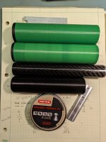
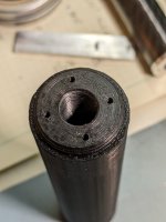
Here's a couple of units I made, with the latest OldSpook design on the bottom. The top two are TPU, the first is solid, the second is 30% gyroid interior baffles, but with solid walls. The third is some early thing I made with PETG interior, CF tube exterior and a nice threaded aluminum piece I made. There's more, my desk is covered with various one's that I have been playing with. You can see the holes that I use to tighten the threaded plug into the tube. For this part I decided on four holes, in case one set of holes got damaged. The pin spanner in the first picture is used to tighten or loosen the plugs.
PXL_20240201_025940311.jpgPXL_20240201_031017870.jpg
Think I will print a 40% gyroid stack in TPU tomorrow. Then a solid TPU stack.
 
  • Like
Reactions: OldSpook
If a thread is 10 times stronger than it needs to be, I think fatigue is not going to be a factor:

Threads printed at the appropriate resolution are amazingly strong. Bob Sterne did tensile tests on 1/2-20 printed threads:

1706762749262.png


There are images of test pieces after breaking them, if you scroll up and down at those links. Earlier in the forum thread are more details about the test piece design, and test procedure.
 
It remains to be seen how strong these threads are, they are after all only about 0.68mm high. (Real number is ~ 25.4/32 * 0.866 ) But they may serve their purpose. I was concerned that if I went too coarse it would seriously weaken the main tube and force me to increase the wall thickness of the tube. My largest collet is 32mm, so I wanted to keep the OD under 32mm for this test. Sometimes the local situation or conditions forces us to make unconventional design choices.