Diana's "ball-sear" trigger was used on the post-war models 25D, 27, 27S, 35, 35S, and 50, from the early 1950's well up into the 80's. The trigger is ingeniously simple, but so unique that it bears some study.
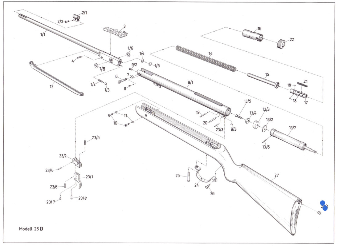
This parts diagram is the model 25D, the smallest member of this family. These part numbers are referenced below (but the part names are just my inventions!).
HOW IT WORKS
1. The inner trigger sleeve (part no. 17) is fixed into position within the receiver, by the two stout cross pins in the action (19 and 20). The three infamous ball bearings (18) sit in holes near the front of the sleeve, which are tapered to let the balls move inward and outward a small amount. The spring guide (15) rests on the front of the inner sleeve.
2. The outer trigger sleeve (16) is the heart of the system. It moves backward when the gun is cocked, and flies forward a short distance when the gun is fired. The firing spring (21) which drives this motion is trapped between the two sleeves.
3. The outer sleeve has three recesses arranged around its center. These have two functions:
+ pushing the ball bearings inward when cocking
+ halting the sleeve's forward motion after firing (they strike the rear of the spring guide)
4. The outer sleeve also has a cut-out underneath, engaged by the two spurs on top of the sear (23/2). This is the actual firing sear, and what you feel when pulling the trigger (contrary to what some famous writers - who should have known better! - have said, the ball bearings have nothing to do with it).
5. Several things happen when cocking the action:
+ The mainspring is compressed as the piston moves rearward
+ The rear of the piston contacts the outer sleeve and pushes it rearward
+ The firing spring is compressed
+ The outer sleeve's recesses contact the ball bearings and push them inward
+ The annular groove around the piston stem comes into line with the ball bearings
6. When the sear engages the outer sleeve's underside recess, all this is locked into place - the ball bearings in their innermost position, restraining the piston. When you pull the trigger, the firing spring pops the outer sleeve forward, instantly releasing the piston by freeing the ball bearings to move outward
STRIPPING THE TRIGGER
+ The inner parts come out with no need to remove the trigger blade, but do pull it back so the sear doesn't intrude into the receiver
+ The mainspring is under some tension even when the gun is uncocked. A spring compressor is absolutely required to keep things under control
+ To disassemble: pull off the sheet metal rear cap; put the gun in the compressor with a little tension on the protruding inner sleeve; drift out the retaining pins. Now pull the trigger and unwind the compressor, the whole mechanism will follow
+ Go slowly with the compressor. Put a rag around the back of the receiver as things come out, to catch any wayward bits
+ To re-assemble: "glue" the ball bearings to the inner sleeve with grease; stack both sleeves on the spring guide; drop this assembly into the mainspring. Pull the trigger and snug up the compressor
+ It's easiest to insert the firing spring after the sleeves are partially pushed past the rear of the receiver, which will help to restrain it
+ Keep the sleeves concentric with the receiver when compressing the spring
+ When re-inserting the cross pins, use a slave pin (a punch or similar) to align the sleeves. It may take some patient wiggling around to get the first pin in
ADJUSTING THE TRIGGER
+ IMPORTANT: the total length of the trigger pull, and the actual pull weight, are fixed! What you adjust is only the transition point between the first and second stages
+ The rear trigger screw (part 23/8) is the actual adjuster. The front screw (23/7) is a lock to keep the adjuster screw from turning (NOTE - the early alloy triggers are the other way around! The FRONT screw is the adjuster, and to change it the rear lock screw must be turned out far enough to clear its head)
+ The end of the adjuster screw strikes the bottom of the receiver tube when the trigger is pulled. This forms the fulcrum for the second stage of the pull
+ To adjust the trigger: loosen the lock screw; turn the adjuster screw as needed; re-tighten the lock screw
+ Turn the adjuster screw in (clockwise) for a longer second stage, or out for a shorter one; work slowly in quarter-turn increments
RANDOM NOTES
+ It is possible to grossly mis-adjust this trigger! If the adjuster screw is too far out, the pull is "all first stage" (a light spongy pull, with no feel for the letoff point). Too far in, it's "all second stage" (a stiff gritty pull that is similarly unpredictable). In other words...when you get that second stage short and crisp - stop!
+ The models 25D and 27 have the trigger as shown. On the models 35 and 50, the same trigger parts are used, but have more room to wiggle around inside the bigger-diameter receiver, so the firing spring adds its own little spring guide
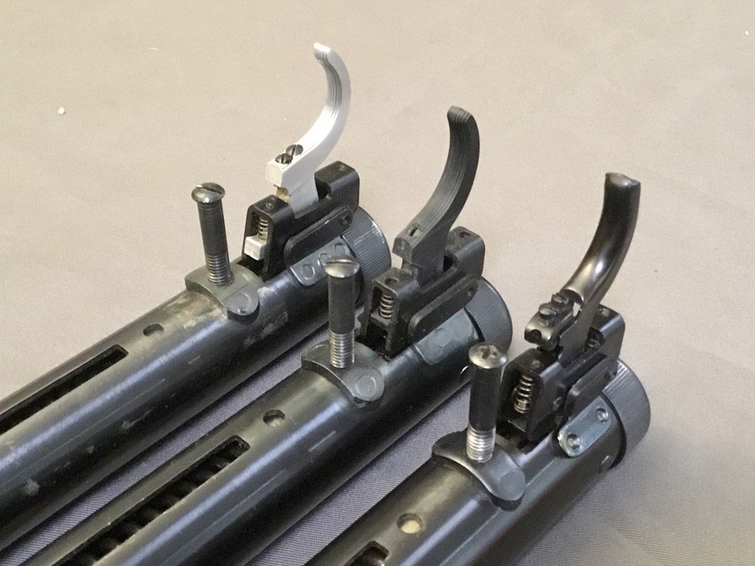
+ Up to about 1964, ball-sear guns had a lovely solid alloy trigger blade; then a plastic one up to the early 70's; finally the stamped steel blade most commonly found today. The adjustments all work the same with one odd exception: the plastic trigger omits the lock screw, as the friction of the adjuster screw against the plastic keeps it from drifting. (Pic is three model 27's)
+ The stamped blade has an interesting improvement. You can easily remove it by drifting out only the first-stage retaining pin (part no. 23/4). On the previous designs, this pin is covered and you must remove the trigger and sear together, by drifting out the second-stage pin (23/3). This unfortunately also frees the extremely stiff second-stage tension spring (23/5)
This parts diagram is the model 25D, the smallest member of this family. These part numbers are referenced below (but the part names are just my inventions!).
HOW IT WORKS
1. The inner trigger sleeve (part no. 17) is fixed into position within the receiver, by the two stout cross pins in the action (19 and 20). The three infamous ball bearings (18) sit in holes near the front of the sleeve, which are tapered to let the balls move inward and outward a small amount. The spring guide (15) rests on the front of the inner sleeve.
2. The outer trigger sleeve (16) is the heart of the system. It moves backward when the gun is cocked, and flies forward a short distance when the gun is fired. The firing spring (21) which drives this motion is trapped between the two sleeves.
3. The outer sleeve has three recesses arranged around its center. These have two functions:
+ pushing the ball bearings inward when cocking
+ halting the sleeve's forward motion after firing (they strike the rear of the spring guide)
4. The outer sleeve also has a cut-out underneath, engaged by the two spurs on top of the sear (23/2). This is the actual firing sear, and what you feel when pulling the trigger (contrary to what some famous writers - who should have known better! - have said, the ball bearings have nothing to do with it).
5. Several things happen when cocking the action:
+ The mainspring is compressed as the piston moves rearward
+ The rear of the piston contacts the outer sleeve and pushes it rearward
+ The firing spring is compressed
+ The outer sleeve's recesses contact the ball bearings and push them inward
+ The annular groove around the piston stem comes into line with the ball bearings
6. When the sear engages the outer sleeve's underside recess, all this is locked into place - the ball bearings in their innermost position, restraining the piston. When you pull the trigger, the firing spring pops the outer sleeve forward, instantly releasing the piston by freeing the ball bearings to move outward
STRIPPING THE TRIGGER
+ The inner parts come out with no need to remove the trigger blade, but do pull it back so the sear doesn't intrude into the receiver
+ The mainspring is under some tension even when the gun is uncocked. A spring compressor is absolutely required to keep things under control
+ To disassemble: pull off the sheet metal rear cap; put the gun in the compressor with a little tension on the protruding inner sleeve; drift out the retaining pins. Now pull the trigger and unwind the compressor, the whole mechanism will follow
+ Go slowly with the compressor. Put a rag around the back of the receiver as things come out, to catch any wayward bits
+ To re-assemble: "glue" the ball bearings to the inner sleeve with grease; stack both sleeves on the spring guide; drop this assembly into the mainspring. Pull the trigger and snug up the compressor
+ It's easiest to insert the firing spring after the sleeves are partially pushed past the rear of the receiver, which will help to restrain it
+ Keep the sleeves concentric with the receiver when compressing the spring
+ When re-inserting the cross pins, use a slave pin (a punch or similar) to align the sleeves. It may take some patient wiggling around to get the first pin in
ADJUSTING THE TRIGGER
+ IMPORTANT: the total length of the trigger pull, and the actual pull weight, are fixed! What you adjust is only the transition point between the first and second stages
+ The rear trigger screw (part 23/8) is the actual adjuster. The front screw (23/7) is a lock to keep the adjuster screw from turning (NOTE - the early alloy triggers are the other way around! The FRONT screw is the adjuster, and to change it the rear lock screw must be turned out far enough to clear its head)
+ The end of the adjuster screw strikes the bottom of the receiver tube when the trigger is pulled. This forms the fulcrum for the second stage of the pull
+ To adjust the trigger: loosen the lock screw; turn the adjuster screw as needed; re-tighten the lock screw
+ Turn the adjuster screw in (clockwise) for a longer second stage, or out for a shorter one; work slowly in quarter-turn increments
RANDOM NOTES
+ It is possible to grossly mis-adjust this trigger! If the adjuster screw is too far out, the pull is "all first stage" (a light spongy pull, with no feel for the letoff point). Too far in, it's "all second stage" (a stiff gritty pull that is similarly unpredictable). In other words...when you get that second stage short and crisp - stop!
+ The models 25D and 27 have the trigger as shown. On the models 35 and 50, the same trigger parts are used, but have more room to wiggle around inside the bigger-diameter receiver, so the firing spring adds its own little spring guide
+ Up to about 1964, ball-sear guns had a lovely solid alloy trigger blade; then a plastic one up to the early 70's; finally the stamped steel blade most commonly found today. The adjustments all work the same with one odd exception: the plastic trigger omits the lock screw, as the friction of the adjuster screw against the plastic keeps it from drifting. (Pic is three model 27's)
+ The stamped blade has an interesting improvement. You can easily remove it by drifting out only the first-stage retaining pin (part no. 23/4). On the previous designs, this pin is covered and you must remove the trigger and sear together, by drifting out the second-stage pin (23/3). This unfortunately also frees the extremely stiff second-stage tension spring (23/5)
Last edited:

